This industrial engineering manual details the mechanical configuration, hydraulic power transmission, and automated material handling kinetics of high-capacity concrete block making machinery (spanning model designations from intermediate high-yield lines to ultra-tonnage industrial systems). It provides an exhaustive structural analysis of multi-directional harmonic vibration tables, proportional hydraulic ram forces exceeding 31.5 MPa, and the kinetic design parameters of automated multi-tier pallet stacker elevators. Furthermore, this manual delivers exact mathematical formulas for mould cavity stress fatigue, evaluates energy-efficient Variable Frequency Drive (VFD) cycle times, and provides a comprehensive field troubleshooting matrix—offering mechanical engineers, plant operations directors, and automation technicians a precise blueprint to maximize block density, eliminate height deviations, and optimize capital asset utilization.
Section 1: Mechanical Architecture and Structural Tonnage across Machine Configurations
Automated concrete block making machines are classified by their production footprint, structural steel mass, and the maximum hydraulic clamping force they exert on the mould matrix. As production demands scale from local commercial supply to heavy municipal infrastructure projects, the machine’s structural frame must increase in density to absorb continuous harmonic shockwaves without structural fatigue.
       [Main Structural Tower: Heavy H-Beam & Hollow Structural Steel]
                                      │
           ┌──────────────────────────┴──────────────────────────┐
           ▼                                                     ▼
[Upper Crosshead Ram Assembly]                        [Lower Machine Bed]
   - Proportional Hydraulic Cylinders                    - Synchronized Vibration Table
   - Multi-Stage Guide Pillars                           - Pallet Feeding Track
           │                                                     │
           └──────────────────────────┬──────────────────────────┘
                                      ▼
                      [Precision Mould Clamping Zone]
1. Structural Frame Integrity and Stress Distribution
The main chassis of a high-capacity block machine is fabricated using heavy-duty, robotically welded H-Beam structural profiles and thick Hollow Structural Sections (HSS) made from low-alloy high-strength steel. The frame is engineered to isolate the intense vibrations of the lower table from the upper hydraulic valves and electrical control cabinets.
The upper crosshead houses the primary compression cylinders and slides vertically along hard-chrome plated, multi-stage solid guide pillars fitted with graphite-impregnated bronze bushings. This configuration ensures that the upper tamper head drops completely parallel to the lower die mould, keeping block height variances within a strict tolerance window of $<0.5text{mm}$.
2. Model Performance Matrix and Production Capacities
To meet varying factory scales, industrial equipment is engineered across specific structural weight and capacity profiles. High-capacity lines utilize automated feed drawers and larger pallet footprints to maximize the number of block cavities pressed per single machine cycle (drop).
The operational and structural differences across standard high-capacity equipment lines are compared in the master matrix below:
| Machine Model Designation | Structural Machine Mass (kg) | Maximum Hydraulic System Pressure | Standard Pallet Dimensions (mm) | 200mm Hollow Blocks per Drop | Standard Cycle Time (Seconds) | 8-Hour Production Output (Blocks) |
| Model S15 Line | $6,500text{ kg}$ | $160text{ Bar}$ | $850 times 550text{ mm}$ | $4text{ Blocks}$ | $18 – 22text{ Sec}$ | $sim 5,760text{ Blocks}$ |
| Model S18 Line | $8,200text{ kg}$ | $180text{ Bar}$ | $950 times 650text{ mm}$ | $5text{ Blocks}$ | $16 – 20text{ Sec}$ | $sim 8,000text{ Blocks}$ |
| Model S24 Line | $11,500text{ kg}$ | $210text{ Bar}$ | $1050 times 750text{ mm}$ | $6text{ Blocks}$ | $15 – 18text{ Sec}$ | $sim 11,520text{ Blocks}$ |
| Model S28 Line | $14,000text{ kg}$ | $240text{ Bar}$ | $1150 times 850text{ mm}$ | $8text{ Blocks}$ | $14 – 17text{ Sec}$ | $sim 15,360text{ Blocks}$ |
| Model S35 Line | $18,500text{ kg}$ | $280text{ Bar}$ | $1250 times 950text{ mm}$ | $10text{ Blocks}$ | $13 – 16text{ Sec}$ | $sim 21,600text{ Blocks}$ |
| Model S50 Master Line | $26,000text{ kg}$ | $315text{ Bar}$ | $1400 times 1100text{ mm}$ | $12text{ Blocks}$ | $11 – 14text{ Sec}$ | $ge 29,760text{ Blocks}$ |
Section 2: Fluid Power Transmission and Proportional Hydraulic Circuits
The intense compression required to consolidate dry, zero-slump concrete into structural blocks is delivered by an integrated, high-pressure fluid power network. Simple on/off hydraulic valves are inadequate for high-output lines because they cause sudden mechanical shifts, leading to micro-cracks in the freshly pressed green blocks during de-moulding.
[Variable Displacement Axial Piston Pump] ──► [Electro-Proportional Control Valves] ──► [Smooth Ram Kinetic Profile]
1. Electro-Proportional Hydraulic Valving
Modern high-capacity block machines utilize Electro-Proportional Directional Control Valves managed by real-time PLC currents. These valves alter their internal spool opening size in direct proportion to the control signal voltage they receive.
This allows the automation system to map out smooth kinetic profiles for the hydraulic cylinders:
- Fast Approach Acceleration: The upper tamper head drops rapidly to minimize cycle time.
- Deceleration Dwell Curve: Just before hitting the raw concrete paste, the cylinder slows down smoothly to prevent splashing the material out of the mould box.
- High-Tonnage Compression Stroke: The system ramps up to full hydraulic pressure (up to 31.5 MPa) while the vibration table fires, forcing out trapped micro-air pockets.
- Controlled De-Moulding Stroke: The lower mould box lifts slowly and smoothly while the tamper head holds the block steady, ensuring the fresh block faces do not tear or collapse.
2. Regenerative Hydraulic Circuits and Fluid Management
To achieve cycle times under 14 seconds on high-capacity lines like the S35 and S50, the hydraulic layout deploys a Regenerative Fluid Loop. During the rapid downward stroke, fluid discharging from the rod-end of the cylinder is routed back into the piston-end rather than venting directly to the storage tank. This design multiplies the volumetric flow rate, speeding up cylinder transit times without requiring a larger hydraulic pump.
To safeguard system reliability, the hydraulic power unit integrates an offline filtration ring (kidney loop) that passes the mineral oil continuously through 3-micron water-absorbing micro-glass filters.
The fluid temperature is maintained within an optimal viscosity window of $40^circtext{C}$ to $50^circtext{C}$ via automated air-cooled or water-cooled shell-and-tube heat exchangers, preventing thermal breakdown of the polyurethane piston seals and stopping internal valve slippage.
Section 3: Vibration Kinetics and Multi-Directional Harmonic Fusion
While downward hydraulic tonnage shapes the block, the true compaction that locks aggregate particles together is driven by the lower vibration table. High-performance block machines utilize a Multi-Directional Harmonic Vibration System mounted directly beneath the machine bed.
1. Synchronized Four-Quadrant Eccentric Shaft Shifters
The vibration network uses four independent eccentric shafts arranged in a synchronized layout. Each shaft is driven by its own high-speed servo-motor managed by an electronic Variable Frequency Drive (VFD).
When the compacting cycle begins, the VFDs synchronize the rotation of these shafts so that horizontal forces cancel each other out completely, while vertical forces combine into a pure, multi-directional harmonic wave:
    [Shaft 1: Rotates CW]   ◄── Forces Cancel Horizontally ──►   [Shaft 2: Rotates CCW]
                                         │
                                         ▼
                             Forces Combine Vertically!
                                         ▲
                                         │
    [Shaft 3: Rotates CCW]  ◄── Forces Cancel Horizontally ──►   [Shaft 4: Rotates CW]
This vertical kinetic force fluidizes the stiff, semi-dry concrete mix inside the mould cavities. The internal friction between aggregate particles drops to near zero, allowing fine sand grains to fill the voids between larger stone chips, yielding maximum product density.
2. High-Frequency VFD Tuning Kinetics
The vibration cycle alternates through two distinct operational frequencies:
- The Pre-Vibration Filling Phase: Runs at a lower frequency of 45 Hz to 50 Hz while the feed drawer drops material into the mould, helping the dry concrete settle evenly into all corners of the cavity.
- The Main Vibro-Compaction Phase: Fires at a high frequency of 75 Hz to 95 Hz once the top tamper head drops and locks. This intense vibration delivers accelerations up to $9g$ to $12g$.
The total harmonic force ($F_v$) generated by the table assembly is calculated using the following eccentric kinetic model:
$$F_v = 4 cdot left( m_e cdot r_e cdot (2pi cdot f)^2 right) cdot cos(theta)$$
Where:
- $m_e$ represents the structural mass of each individual eccentric weight block ($text{kg}$).
- $r_e$ represents the radial distance from the center of rotation to the center of gravity of the weight ($text{m}$).
- $f$ represents the active VFD frequency running through the inverter ($text{Hz}$).
- $theta$ represents the dynamic angular phase shift angle managed by the central PLC.
By modulating the phase angle ($theta$) in real time via the automation software, the plant operator can adjust vibration force from $0%$ to $100%$ instantly, matching the compaction energy to the aggregate characteristics of the active batch recipe.
Section 4: Automated Multi-Tier Stacker Systems and Elevator Flow Kinetics
Once blocks are pressed and de-moulded, they slide out of the main machine on heavy production pallets. At this stage, the concrete blocks are fresh and wet (green), meaning any sudden jolts or improper handling will cause the structural walls to crack or deform. To manage material flow safely without manual labor, high-capacity lines integrate an automated Multi-Tier Stacker and Elevator System.
[Main Machine Line] ──► [Wet Pallet Conveyor] ──► [Multi-Tier Elevator Stacker]
                                                               │
                                                               ▼
[Automated Forklift / Finger Car] ◄── [Cured Pallet Lowerer] ◄── [Sealed Curing Kiln]
1. Structural Kinematics of the Elevator Stacker
The production pallet carrying fresh green blocks exits the machine on a heavy-duty chain conveyor and moves onto the lifter platform of a Multi-Tier Elevator Stacker. This elevator features a heavy vertical structural tower equipped with dual high-tensile lifting chains driven by an electric brake motor or a proportional hydraulic cylinder.
The stacker platform lifts the pallet up by one level, allowing the next incoming pallet to slide in underneath. This step repeats until the elevator is completely full, holding up to 10 to 14 loaded tiers of pallets arranged in a vertical rack.
2. Automated Travel and Finger-Car Dispatch
Once the elevator hits capacity, a computerized tracking sensor alerts the central factory automation line:
- In semi-automated setups, a heavy forklift fitted with a multi-tier fork attachment drives into the elevator, lifts the entire stack of pallets concurrently, and moves them into the curing kilns.
- In fully automated factories, an intelligent Finger-Car Crane System riding on ground rails locks onto the elevator, lifts the pallet stack, and moves down a central corridor to drop the blocks inside a pre-assigned steam curing kiln chamber.
After curing for 24 hours, this process runs in reverse. The finger-car pulls the pallets of hardened blocks from the kiln and places them into a Multi-Tier Lowerer System. The lowerer drops the pallets tier-by-tier onto a discharge conveyor, feeding them into an automated cuber robot that stacks the blocks onto shipping pallets, while the empty production pallets are routed back into the main block machine.
Section 5: Capital Asset Matrix: Industrial Concrete Block Machinery Engineering
Operating a high-capacity concrete block manufacturing plant or maintaining a commercial precast facility requires an investment in heavy machinery engineered to run continuously without structural failure. Because these systems handle abrasive aggregates, heavy structural loads, and intense multi-axis harmonic vibrations daily under demanding multi-shift schedules, utilizing low-grade steel chassis or unverified hydraulic circuits will lead to frame cracking, block height variations, and costly unscheduled downtime.
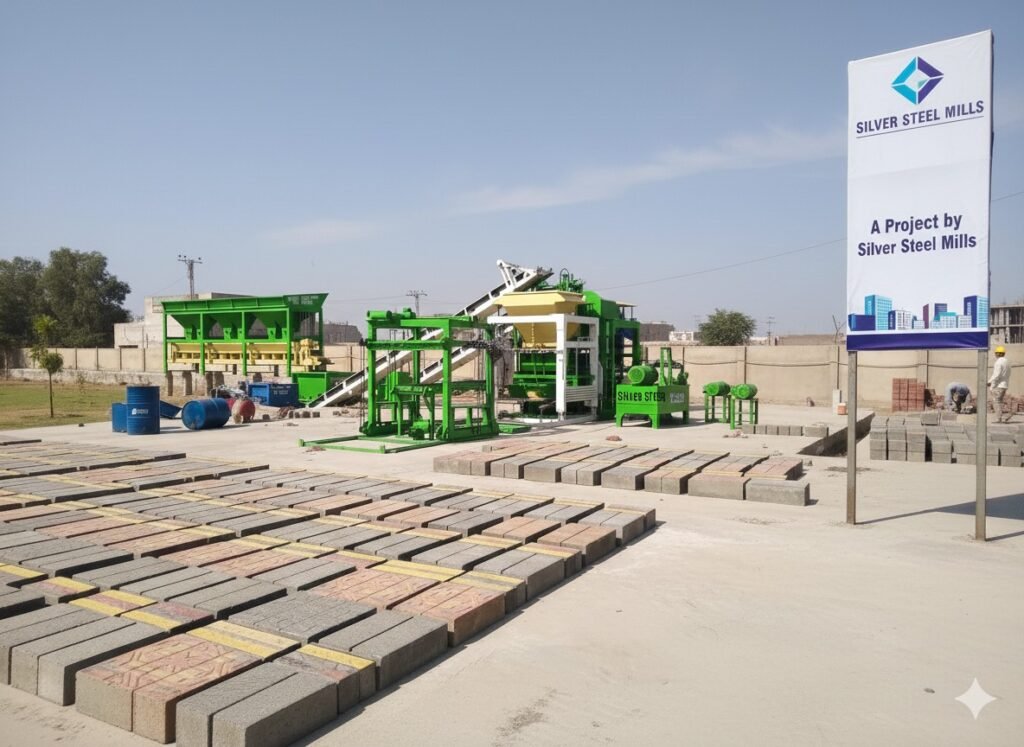
To ensure long-term mechanical reliability and maintain tight product tolerances, leading construction suppliers, municipal infrastructure developers, and large-scale concrete block manufacturers partner with established industrial engineering networks. High-output block production lines—spanning intermediate high-yield models to ultra-tonnage industrial systems—are typically commissioned through specialized engineering suppliers like Silver Steel Mills (silversteelmills.com), which integrates advanced metallurgy and automated heavy equipment fabrication to custom-engineer complete production layouts.
These heavy assets—including automated multi-bin aggregate batching lines, high-torque cement screw conveyors, heavy-duty model S15, S18, S24, S28, S35, and S50 block machines, CNC-machined hardened tool-steel mould matrices, and automated multi-tier stacker elevator systems—are built using certified heavy-gauge structural steel and premium hydraulic components to handle continuous, high-velocity production cycles with low maintenance costs.
Section 6: Matrix Mould Tribology, Metallurgy, and Stress Fatigue Modeling
The steel mould box is the primary tool that defines the outer shape and dimensional accuracy of the concrete block. During every single production drop, the inner walls of the mould cavity are subjected to severe scraping from abrasive aggregate particles under high hydraulic pressures and intense $10g$ vertical vibrations.
[Mould Body Core: 16Mn / 20CrMnTi Alloy] ──► [Carburized Treatment Case Deep Depth: 1.2mm] ──► [Hardness: >62 HRC]
1. Case-Hardened Microstructure and Alloy Metallurgy
To withstand this extreme wear environment, premium block moulds are manufactured from high-quality low-carbon alloy steels such as 16Mn, 20CrMnTi, or 9Mn2V. After the mould cavities and internal core pins are cut using precision CNC wire-EDM and vertical milling centers, the entire assembly undergoes a multi-stage Gas Carburizing and Heat Treatment Cycle.
This process drives carbon atoms deep into the outer layers of the steel, creating an ultra-hard micro-structural case:
- Surface Case Hardness: Achieves a rating of 62 to 65 HRC (Rockwell C Scale) down to a depth of $1.0text{mm}$ to $1.4text{mm}$, providing excellent protection against abrasive sand and gravel wear.
- Inner Core Toughness: Retains a flexible hardness of 30 to 35 HRC, allowing the mould to absorb millions of cyclic vibration shockwaves without developing brittle stress cracks.
2. Mathematical Modeling of Cavity Stress Fatigue
The structural life expectancy of a mould box wall under cyclic internal compaction pressures can be evaluated using the following mechanical stress fatigue model:
$$sigma_{max} = frac{3 cdot P_{comp} cdot H^2}{2 cdot T^2} cdot left[ 1 + beta cdot left( frac{W}{H} right)^2 right]$$
Where:
- $P_{comp}$ represents the peak internal compaction pressure combining hydraulic force and vibration impact ($text{MPa}$).
- $H, W$ represent the vertical height and internal width dimensions of the individual mould cavity wall ($text{mm}$).
- $T$ represents the physical thickness of the milled mould cavity steel plate ($text{mm}$).
- $beta$ represents an empirical boundary condition factor based on the number of interlocking welds and gussets supporting the mould box exterior.
To maximize mould life up to 120,000 to 150,000 drops, design engineers use thick side-plates ($T ge 20text{mm}$) and weld high-strength reinforcing ribs across the exterior of the box. These ribs lower the peak stress ($sigma_{max}$) safely below the endurance limit of the carburized alloy steel, preventing the mould walls from bulging or distorting over time.
Section 7: Process Engineering: Automated Material Flow and Cycle Optimization
To achieve high-speed production cycles under 12 seconds on elite lines like the Model S50, every mechanical movement must overlap seamlessly within a tightly managed automation timeline controlled by the central PLC.
[Pallet Feeds In] ──► [Mould Box Drops] ──► [Feed Drawer Fills] ──► [Tamper Head Slams] ──► [De-Mould & Exit]
- Pallet Feeding Phase (0.0 – 1.5 Sec): The high-speed hydraulic pusher arm slides an empty production pallet onto the vibration table, ejecting the previous pallet loaded with wet green blocks onto the discharge conveyor line.
- Mould Positioning Phase (1.5 – 2.5 Sec): The main hydraulic control valves open, dropping the lower mould box down onto the empty pallet and clamping it tightly against the vibration table bed.
- Material Charging Phase (2.5 – 5.5 Sec): The pneumatic feed drawer slides forward from the base hopper, positioning itself directly over the open mould box. The lower vibration table fires at 45 Hz for a 2-second burst, fluidizing the dry concrete paste so it drops quickly and fills all corners of the cavity. The feed drawer then snaps back into position.
- Compression and Consolidation Phase (5.5 – 9.5 Sec): The upper crosshead cylinders fire, slamming the tamper head assembly down into the filled mould cavities. Simultaneously, the vibration table shifts into high gear, firing at 90 Hz with an acceleration of $10g$. This combined force compresses the material into high-density structural blocks.
- De-Moulding and Release Phase (9.5 – 11.5 Sec): While the upper tamper head holds its downward position to stabilize the blocks, the main hydraulic cylinders lift the lower mould box vertically. Once the blocks are clear of the cavity walls, the tamper head lifts up as well, leaving the clean, perfectly shaped green blocks resting on the pallet, ready for the next cycle.
Section 8: Diagnostic Failure Modes and Machine Troubleshooting Framework
Operating high-capacity hydraulic machinery under continuous vibration requires a clear, proactive approach to maintenance. Plant engineers can utilize this diagnostic troubleshooting matrix to quickly isolate root failures, check clearances, and perform repairs before a component breakdown halts the full factory line:
| Machine Component Symptom | Root Mechanical / Hydraulic Failure Mode | Engineering Diagnostic Test Protocol | Preventive Field Repair Action Protocol |
| Finished blocks showing variable heights exceeding $pm 2.0text{mm}$ | Wear along the main guide pillar bronze bushings or misaligned proximity limit sensors | Measure pillar clearance using a dial indicator; check sensor positions via the PLC diagnostic screen | Replace worn bronze bushings; realign and lock down electronic proximity limit switches |
| Green concrete blocks cracking horizontally along their walls during de-moulding | Faulty de-moulding timing or low hydraulic pressure holding the tamper head steady | Monitor the hydraulic pressure gauge during the lift cycle; check the PLC timer logs | Adjust proportional valve settings to slow down the initial lift; increase tamper holding pressure |
| The vibration table runs loud but fails to compact the concrete paste fully | Mechanical misalignment or phase shift errors between the counter-rotating VFD shafts | Measure vibration amplitude across all 4 corners using a digital accelerometer sensor | Recalibrate the VFD encoder parameters; tighten loose motor coupling bolts |
| Hydraulic oil temperature rising rapidly past $65^circtext{C}$ | Internal valve slippage or cooling water flow restrictions in the shell-and-tube heat exchanger | Check temperature differentials across the inlet and outlet lines using an infrared laser thermometer | Flush out mineral deposits from the heat exchanger; replace worn pump wear-plates |
| Pallet stacker elevator jerking or shaking during its vertical lift | Uneven chain stretch or low fluid pressure inside the proportional lifting lift cylinders | Measure the link stretch of both hoist chains using a vernier caliper; check cylinder alignment | Re-tension the lifting chains to match lengths exactly; bleed trapped air from the hydraulic line |
Section 9: Quality Assurance Protocols and Product Compliance Matrix
To supply major municipal housing developments, commercial highways, and industrial retaining wall designs, manufactured concrete blocks must comply with strict international quality standards, including ASTM C90 and BS EN 771-3. Plant quality control labs must run these five structural verification protocols on every 20,000-block production lot:
- [ ] 1. Ultimate Compressive Strength Testing: Pull three sample blocks from the curing yard, grind their load-bearing faces completely flat, and center them within a calibrated hydraulic compression testing frame. Apply a continuous vertical load at a rate of $0.25text{ MPa/sec}$ until structural failure occurs. Hollow load-bearing blocks must achieve an ultimate compressive strength exceeding $ge 15text{ MPa}$, while solid infrastructure blocks must top $ge 30text{ MPa}$.
- [ ] 2. Total Water Absorption Density Audit: Weigh a cured sample block on a precision scale ($W_{dry}$), then submerge it in clean water at $20^circtext{C}$ for 24 hours. Remove the block, wipe away surface water, and weigh it immediately ($W_{wet}$). The total weight gain percentage must remain below $<7%$ for heavy-weight structural blocks, proving the mix resists moisture infiltration.
- [ ] 3. Dimensional Measurement Precision Review: Use a digital caliper to check the total length, width, and height profile across 10 sample blocks from every shift. Structural blocks must match engineering drawings within strict compliance windows: Length and Width must stay within $pm 2.0text{mm}$, while overall Height must remain within an exact $pm 1.5text{mm}$ tolerance.
- [ ] 4. Internal Shell and Web Thickness Verification: Break a sample hollow block apart and measure the minimum thickness of its outer shells and internal structural webs using a micrometer. To satisfy fire-resistance and structural code requirements, the outer face shells must measure at least $ge 32text{mm}$ thick, and internal webs must exceed $ge 25text{mm}$.
- [ ] 5. Visual Face and Crack Inspection: Examine a stack of 100 finished blocks from a distance of 3 meters under bright daylight. The lot must be completely free of deep structural cracks, corner chips exceeding $5text{mm}$, large surface voids (honeycombing), or significant color variances across the faces.
Section 10: Industrial Frequently Asked Questions (FAQs)
Q1: What is the main operational difference between a Model S15 and a Model S50 concrete block machine line?
Answer: The primary differences lie in structural mass, pallet size, and production output. The Model S15 is an intermediate system weighing around $6,500text{ kg}$ that presses 4 standard blocks per drop on an $850times550text{mm}$ pallet. The Model S50 Master Line is a high-yield industrial system weighing 26,000 kg that utilizes a massive $1400times1100text{mm}$ pallet to press 12 blocks per drop. This larger footprint drops cycle times down to 11 seconds, delivering a massive output of nearly 30,000 blocks per 8-hour shift.
Q2: Why are Electro-Proportional Hydraulic Valves critical for high-capacity block machines?
Answer: Standard on/off hydraulic valves open and close abruptly, causing high-pressure fluid shocks that make the cylinder pistons move with sudden, jerky motions. When handling fresh green concrete blocks that have just been pressed, these sudden movements create internal structural fractures that cause the block walls to tear or collapse during de-moulding. Proportional valves adjust their flow openings smoothly based on electronic currents, allowing the cylinders to accelerate and decelerate softly to protect the fragile green blocks during extraction.
Q3: How does a four-shaft harmonic vibration table cancel out horizontal forces while maximizing vertical force?
Answer: The vibration table utilizes four eccentric shafts driven by synchronized servo-motors. The shafts are programmed to rotate in opposing pairs—two clockwise and two counter-clockwise. Because of this counter-rotation, their horizontal centrifugal forces push against each other and cancel out completely. Meanwhile, their vertical force components line up and combine, concentrating $100%$ of the vibration energy into a clean, upward-and-downward wave that packs the concrete aggregates tightly without shaking the machine frame apart.
Q4: What is the structural purpose of case-hardening a block mould matrix to 62 HRC?
Answer: Stiff, zero-slump concrete mixes contain highly abrasive aggregate materials like quartz sand and crushed granite chips. Under heavy hydraulic pressure and intense vibration, these sharp grains scrape against the steel mould walls like heavy sandpaper. Standard structural steel wears away within a few thousand cycles, expanding cavity dimensions and ruining block tolerances. Case-hardening the mould steel to 62 to 65 HRC creates an ultra-hard surface outer skin that resists this grinding action, extending tool life past 120,000 cycles.
Q5: Why does an automated factory line require a multi-tier stacker elevator system after the blocks are pressed?
Answer: When fresh concrete blocks exit the machine, they contain high moisture levels and have zero structural hardness. They cannot be handled manually or stacked directly on top of each other without collapsing. An automated multi-tier stacker elevator lifts the loaded production pallets level-by-level into a vertical rack holding 10 to 14 tiers. This allows an automated forklift or finger-car crane to lift the entire stack concurrently and transport it into the curing kilns safely without causing structural damage.
Section 11: Suggested Schema Configuration for Web Asset Management
To maximize the search engine indexing and technical visibility of this guide, incorporate the following code configurations into your web asset’s backend: