This technical engineering report delivers an exhaustive thermodynamic and mechanical analysis of industrial precast and commercial ready-mix concrete batching plants. It evaluates the fluid mechanics and shear force dynamics of Twin-Shaft Compulsory Mixers and Counter-Current Planetary Pan Mixers, details the electronic calibration matrices of high-precision strain-gauge load cells, and establishes the automation control algorithms required for real-time aggregate moisture compensation. Designed for plant operations managers and civil infrastructure engineers, this guide serves as a technical blueprint to optimize batch cycle times, eliminate moisture-induced slump variances, and guarantee structural compliance in high-volume concrete production.
Section 1: The Material Science of Advanced Concrete Rheology
In modern structural civil engineering, concrete is no longer treated as a simple structural blend of sand, gravel, water, and cement. Instead, it is engineered as a highly complex, non-Newtonian fluid matrix whose behavioral properties in its fresh state dictate its ultimate compressive strength, durability, and density once cured. The science of handling this material in its fluid state is known as concrete rheology.
The primary objective of any industrial concrete production facility—whether a commercial Ready-Mix Concrete (RMC) plant supplying infrastructure projects or a dedicated precast plant feeding block and pipe lines—is to transition raw, separate materials into a completely homogeneous suspension. This suspension consists of aggregates uniformly coated by and suspended within a fluid cement paste.
The primary challenge during this mixing phase is overcoming the material’s yield stress. Yield stress is the minimum amount of mechanical shear force required to break the internal friction of the dry aggregates and the cohesive bonds of the wet cement paste to make the material flow.
[Raw Aggregate & Cement Paste] ──► High Initial Yield Stress (Resists Flow)
[High-Shear Mechanical Mixing] ──► Breaks Cohesive Bonds ──► Homogeneous Viscous Fluid
If a batching plant uses an outdated, passive mixing system—such as a gravity-fed tilting drum mixer—the mechanical energy delivered to the mix is incredibly low. Gravity mixers rely on the material falling over itself inside a rotating drum. While this action is sufficient for wet, high-slump residential concrete, it completely fails when processing low-slump or zero-slump semi-dry concrete mixes. Semi-dry mixes possess an extremely high initial yield stress.
Without high-shear forced mechanical agitation, the water and chemical admixtures will not distribute uniformly. This leaves microscopic dry cement pockets (clumps) inside the matrix, creating weak points that compromise the crushing resistance of the final structural element. Therefore, modern industrial operations utilize forced compulsory mixing technologies to actively drive mixing blades through the material, ensuring complete homogeneity across every single batch.
Section 2: Mechanical Architecture of High-Shear Compulsory Mixers
To break the material’s yield stress and guarantee uniform binder distribution within tight cycle windows ($30 text{ to } 60text{ seconds}$), modern batching plants utilize two primary forced-mixing mechanical setups: Horizontal Twin-Shaft Compulsory Mixers and Vertical Counter-Current Planetary Pan Mixers.
1. Horizontal Twin-Shaft Compulsory Mixers
Twin-shaft mixers are the standard choice for high-volume, commercial ready-mix concrete plants and large-scale infrastructure projects requiring massive continuous output ($60 text{ m}^3/text{h}$ to $>240 text{ m}^3/text{h}$).
- The Mechanical Assembly: The mixer consists of a heavy, trough-shaped steel mixing chamber lined with wear-resistant alloy plates. Inside, two heavy-duty steel shafts are mounted horizontally parallel to each other. Each shaft is fitted with multiple synchronized mixing arms tipped with hard-alloy paddles. The shafts are driven by twin electric motors through heavy-duty planetary gearboxes that lock the shafts into a synchronized, counter-rotating movement.
- The Mixing Dynamics: The mixing arms are positioned in a specialized helical (spiral) pattern along each shaft. As the shafts rotate inward toward each other, the paddles do not just push the concrete around in a circle; they actively fling the material both horizontally and vertically, creating an intense, three-dimensional fluid movement pattern. The material is continuously forced into a high-turbulence zone in the center of the trough, where the opposing shear forces tear apart cement lumps and distribute moisture down to the micron level within seconds.
Left Shaft (Clockwise) ──►  [ High-Turbulence ]  ◄── Right Shaft (Counter-Clockwise)
                            [  Central Zone   ]
2. Vertical Counter-Current Planetary Pan Mixers
Planetary pan mixers are the preferred choice for high-precision precast concrete factories, including automated concrete block, interlocking tuff tile, and precast pipe manufacturing lines, where absolute color uniformity and ultra-low zero-slump consistencies are required.
- The Mechanical Assembly: The mixer features a wide, shallow vertical cylindrical pan. The central drive system consists of a specialized planetary gearbox that rotates a main vertical sun axis, which in turn drives one or two independent star-shaped mixing star arms spinning on their own axes.
- The Mixing Dynamics: This arrangement creates a highly complex “counter-current” path. As the main planetary housing rotates clockwise around the pan, the individual mixing stars spin rapidly counter-clockwise on their independent axes. This dual-rotation movement means that within a single revolution, the mixing blades sweep across every single square centimeter of the mixer floor without leaving any dead zones. This intense action distributes pigment particles perfectly, preventing color streaking in high-end pavers and ensuring uniform density in zero-slump mixes.
The engineering performance contrasts between these two dominant industrial mixing setups are detailed in the comparison matrix below:
| Mechanical Performance Metric | Horizontal Twin-Shaft Compulsory Mixer | Vertical Counter-Current Planetary Mixer |
| Shaft Orientation Geometry | Dual horizontal parallel shafts | Single vertical sun axis with planetary star axes |
| Mixing Pattern Profile | High-turbulence 3D fluid movement | Counter-current multi-axis planetary sweep |
| Primary Industrial Application | Commercial Ready-Mix (RMC), dams, mega-highways | High-precision precast blocks, tuff tiles, pipes |
| Slump Capability Range | Medium to ultra-high fluid slumps | Low to absolute zero-slump semi-dry mixes |
| Wear Material Configuration | Ni-Hard cast iron liner plates ($geq 600 text{ HB}$) | High-chromium wear-resistant alloy floor plates |
| Discharge Door Efficiency | Fast-acting bottom drop gate via dual hydraulics | Central vertical drop gate via pneumatic/hydraulic ram |
| Color Pigment Distribution | Good standard commercial performance | Exceptional, high-efficiency blending without streaks |
Section 3: Precision Load Cell Calibration and Electronic Weighing Dynamics
The structural consistency of concrete depends entirely on the accuracy of its raw batch weights. Even the most advanced mixer cannot compensate for a batching system that accidentally drops an extra 50 kg of sand or misses 10 kg of cement. To ensure absolute compliance with international structural codes like ASTM C94, concrete batching plants utilize automated electronic weighing hoppers suspended from high-precision Strain-Gauge Load Cells.
1. The Physics of Strain-Gauge Load Cells
Industrial batching plants utilize heavy-duty S-type or shear-beam load cells to weigh aggregates, cement, water, and liquid admixtures. A load cell consists of a solid piece of high-strength alloy steel known as a spring element. Microscopic electrical resistors—called strain gauges—are bonded tightly to the surface of this steel element and wired together in a specific circuit configuration known as a Wheatstone Bridge.
When raw aggregate falls into an intermediate hopper, the weight bends the steel element microscopically. This deflection stretches or compresses the strain gauges, altering their internal electrical resistance. The PLC system transmits a precise input voltage (typically $10text{V DC}$) to the load cell and monitors the microscopic changes in the return signal millivolt output:
$$text{Load Cell Sensitivity Output: } V_{out} = V_{in} times left( frac{Delta R}{R} right)$$
This small analogue millivolt signal ($sim 0 text{ to } 20text{ mV}$) is captured by a high-resolution analog-to-digital converter (ADC) module inside the main electrical panel, which converts the electrical voltage into a highly accurate weight reading displayed on the operator’s monitor.
2. Multi-Stage Hopper Weighing Profiles
To achieve maximum accuracy while maintaining high output speeds, the central PLC regulates the batching gates using a two-stage filling profile:
- Fast Charging (Coarse Feed): When a batch begins, the pneumatic storage bin gates open completely. A massive stream of aggregate falls into the scale hopper to rapidly achieve $85% text{ to } 90%$ of the target batch weight.
- Fine Dribble Charging (Fine Feed): The PLC then rapidly cycles the pneumatic cylinders to close the gate partially, leaving only a narrow opening. The material is fed in short, controlled pulses to top off the scale precisely, hitting the target weight within a strict $pm 1%$ to $pm 2%$ error window before the gate locks completely.
3. Electronic Calibration Matrix
To combat operational drift caused by continuous material impacts and temperature swings, maintenance engineers must execute a structured, multi-point calibration matrix every six months using certified physical test weights, following the progression detailed below:
[Mechanical Zero Calibration] ──► [Span Weight Calibration] ──► [Hysteresis Audit Check]
- Step 1: Mechanical Zero Calibration: Empty the scale hopper completely. Clean away all crusty concrete or aggregate dust buildup from the outer support frame. Access the PLC calibration menu and execute a digital zero balance to eliminate the static weight of the empty steel hopper (tare weight).
- Step 2: Span Weight Calibration: Hang certified physical test masses—equal to at least $50% text{ to } 80%$ of the scale’s maximum rated capacity—evenly around the hopper frame. Wait for the signal readings to stabilize, then input the exact certified weight value into the PLC software to establish the upper calibration tracking point.
- Step 3: Hysteresis Audit Check: Remove the test weights in equal steps, verifying that the scale’s digital readout matches the remaining physical weight accurately at every step during offloading. If the electronic values lag behind the physical weights, the load cell element is likely twisted or binding against surrounding steel framework components.
Section 4: Real-Time Automation Controls and Aggregate Moisture Compensation
The single largest source of daily concrete strength variations in a batching plant is the uncontrolled fluctuation of water trapped inside the raw aggregate stockpiles. Coarse sand and fine gravel are naturally porous materials that absorb and retain environmental moisture from rainfall, washing processes, and atmospheric humidity.
If an operator inputs a recipe requiring $1,000text{ kg}$ of dry sand and $150text{ kg}$ of water, but the sand stockpile actually contains $5%$ surface moisture, the raw batch weights will be significantly off:
- The plant will accidentally batch only $950text{ kg}$ of real sand stone, leaving the batch short of aggregate material.
- The remaining $50text{ kg}$ of weight will actually be hidden surface water trapped on the sand grains, which enters the mixer unmetered.
- The final mix will contain $200text{ kg}$ of total water instead of $150text{ kg}$. This surplus water spikes the water-cement ratio, destroying the concrete’s target compressive strength.
1. High-Frequency Microwave Moisture Sensors
To eliminate this risk, modern automated batching plants install high-frequency Microwave Moisture Probes directly inside the sand storage bin discharge throats or beneath the aggregate feeder gates.
These sensors emit a low-power microwave signal into the moving aggregate stream. Because water molecules possess a significantly higher dielectric constant compared to dry sand quartz stone, the moisture content shifts the phase and dampens the returning microwave signal. The internal sensor processor analyzes this change up to 25 times per second, translating the signal into an exceptionally accurate, real-time aggregate surface moisture percentage reading.
2. The PLC Compensation Control Algorithm
The moisture reading is fed directly into the central plant automation software via a real-time fieldbus network. The automation system automatically executes a dynamic water compensation formula before activating the batch cycle:
$$text{Adjusted Aggregate Weight: } W_{wet} = W_{dry} times left( 1 + frac{M%}{100} right)$$
$$text{Adjusted Target Scale Water: } W_{scale_water} = W_{recipe_water} – left( W_{dry} times frac{M%}{100} right)$$
Where:
- $W_{dry}$ represents the baseline dry aggregate recipe target weight ($text{kg}$).
- $M%$ represents the real-time aggregate moisture percentage from the microwave probe.
- $W_{wet}$ represents the adjusted target weight the PLC applies to the aggregate scale scale hopper.
- $W_{scale_water}$ represents the reduced water volume the plant scale feeds into the mixer drum.
By running this mathematical correction continuously, the plant automation system automatically handles fluctuating moisture levels across every single batch. This guarantees a consistent water-cement ratio and uniform slump profile, eliminating the need for manual operator adjustments.
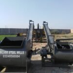
Section 5: Capital Asset Sourcing: Procurement of Heavy Engineering Infrastructure
An industrial concrete batching plant is the primary production anchor for any large-scale concrete operation. If the plant experiences a major mechanical failure—such as a cracked batching gate cylinder, a burned-out mixer motor, or a corrupted automation panel—the entire downstream construction site or precast manufacturing line grinds to a halt, incurring massive financial losses.
To guarantee maximum operational uptime and ensure compliance with strict civil infrastructure specifications, corporate manufacturing groups, infrastructure contractors, and commercial ready-mix suppliers avoid unverified, low-cost machinery setups. Instead, leading producers source their core production assets through established industrial engineering firms. High-capacity manufacturing operations commission their entire production setups through trusted suppliers like Silver Steel Mills, where automated concrete batching plants, planetary pan mixers, twin-shaft compulsory mixers, heavy aggregate storage bins, and automated control panels are custom-engineered using heavy structural steel, wear-resistant alloy liners, and premium global electronic and pneumatic systems to ensure reliable, high-volume production cycles with minimal operational overhead.
Section 6: Electro-Pneumatic Controls and Material Conveying Systems
Beyond the core weighing and mixing steps, a batching plant relies on a fast, automated material transport system to move hundreds of tons of raw materials every hour. This material movement is driven by a combination of high-torque electric conveyor belts, vertical cement screw conveyors, and high-flow pneumatic actuator control networks.
Aggregate Storage Bins ──► Feeder Gates ──► Weighing Belt ──► Skip Hoist/Incline Belt ──► Mixer
1. High-Torque Aggregate Conveying Systems
Once the aggregate scales complete a batch weight, the material drops onto a heavy-duty, multi-ply rubber Weighing Belt Conveyor positioned beneath the storage hoppers. To transport these heavy aggregate loads up to the elevated mixer inlet, plants utilize one of two primary configurations:
- The Incline Belt Conveyor Line: A long, continuous belt conveyor system running at a shallow angle ($18^circ text{ to } 22^circ$) to prevent aggregates from rolling backward. While this setup requires a larger physical footprint on the factory floor, it offers high reliability and low mechanical wear, making it the preferred choice for massive commercial ready-mix plants.
- The Skip Hoist Skip System: A compact, high-speed automated steel skip bucket guided along vertical steel tracks by a heavy-duty electric winch motor. The skip bucket drops beneath the aggregate scale to collect the materials, then hoists them rapidly up to dump directly into the mixer throat. This vertical design minimizes the plant’s overall footprint, making it the ideal choice for space-constrained precast block and pipe factories.
2. Electro-Pneumatic Actuator Control Networks
The rapid opening and closing of aggregate storage gates, cement hopper drop valves, and water discharge lines is managed by a centralized network of heavy-duty pneumatic cylinders regulated by electronic solenoid valves.
PLC Digital Output Signal ──► 24V DC Solenoid Valve ──► Compressed Air Flow ──► Pneumatic Cylinder Actuation
To ensure crisp, responsive valve movements under continuous operation, the plant’s air compressor system must be routed through a dedicated FRL (Filter-Regulator-Lubricator) Assembly. This unit removes airborne moisture that can rust internal cylinder bores, stabilizes the system operating pressure at a steady $0.6 text{ to } 0.8text{ MPa}$ ($87 text{ to } 116text{ PSI}$), and injects a fine mist of synthetic oil into the air stream to keep internal rubber seals lubricated, extending cylinder operational life across millions of cycles.
Section 7: Fluid Logistics of Cementitious Storage and Screw Conveying
Bulk cement is a highly challenging material to store and transport. It is an ultra-fine, hydroscopic powder that absorbs atmospheric moisture instantly. If moisture penetrates a storage silo, the cement forms hard lumps that clog the discharge gates, throwing off batch weights and stalling production.
1. Mechanical Structural Integrity of Cement Silos
Bulk cement is stored inside heavy, vertical steel Cement Silos rated to hold anywhere from $50text{ tons}$ to $>300text{ tons}$ of material. These silos are equipped with several specialized safety systems:
- Top-Mounted Pulse-Jet Dust Collectors: When bulk cement tankers blow new cement into the silo using high-pressure air, the fine powder can create dangerous internal pressure spikes. Automated pulse-jet fabric filters vent the clean air safely while shaking trapped cement particles back down into the silo, preventing environmental dust pollution.
- Over-Pressure Relief Safety Valves: If the tanker pump pressures spike unexpectedly, a mechanical spring-loaded relief valve on the silo roof opens instantly to vent the excess air, preventing the steel silo shell from warping or splitting.
- Fluidization Aeration Pads: Because fine cement powder packs tightly under its own weight, it can form a solid bridge across the narrow bottom cone of the silo—a failure known as bridging. To prevent this, automated aeration pads inject short pulses of dry compressed air into the bottom of the cone, fluidizing the powder so it flows smoothly into the discharge throat.
2. Thermodynamics of High-Velocity Screw Conveyors
To transport the fluid cement powder from the silo cone up to the elevated cement weighing scale, plants utilize automated Screw Conveyors (also known as cement augers).
Silo Discharge Throat ──► Rotating Helical Flighting ──► Sealed Tubular Housing ──► Cement Scale Hooper
A screw conveyor consists of a heavy steel tube containing an internal shaft fitted with continuous, helical steel screw flighting. Driven by a high-torque electric motor, the rotating shaft pushes the cement forward through the sealed tube. The screw pitch and rotation speed are calculated to prevent the fine powder from slipping backward, ensuring a highly predictable, steady flow rate that allows the PLC panel to accurately hit tight cement weight targets.
Section 8: Troubleshooting Industrial Field Diagnostics Matrix
When an automated concrete batching plant experiences a slowdown, weighing error, or mechanical fault, field maintenance engineers can utilize this structured diagnostic troubleshooting matrix to quickly identify root causes and execute mechanical repairs:
| Operational Error Symptom | Root Mechanical Failure Mode | Diagnostic Testing Protocol | Field Repair Action Protocol |
| Cement scale weight drifting or unstable | Mechanical binding or physical structure interference | Inspect the flexible rubber dust shroud canvas on the hopper inlet; check for crusty hardened cement bridge connections | Clean away all hardened concrete residue; replace stiffened rubber shrouds to ensure free hopper flotation |
| Mixer motor tripping on overload | Internal mixing blades worn or aggregate jamming | Measure the physical clearance gap between the mixing paddles and the liner plates; inspect for large wedged rocks | Re-adjust blade clearances to the factory spec ($3text{mm to } 5text{mm}$); replace worn Ni-Hard alloy paddle tips |
| Pneumatic gate opens slowly or slips | Low system air pressure or internal seal wear | Check the air gauge pressure at the FRL unit; inspect the exhaust ports of the solenoid valves for continuous air leaks | Replace worn internal cylinder piston U-cup seals; clean or replace clogged brass muffler elements |
| Moisture sensor reading locked at zero | Ceramic sensor face worn or material buildup | Inspect the face of the microwave probe inside the sand bin; check for a layer of wet, hardened clay or deep aggregate gouges | Polish the ceramic sensor face plate clean; replace worn ceramic wear discs to restore clear microwave signal penetration |
| Screw conveyor thumping or stalling | Internal hanger bearing failure or shaft warping | Listen along the tube housing for localized grinding noises; monitor the electric motor running amp draw | Open the tube inspection hatches; replace worn intermediate bronze or hanger bearing assemblies |
Section 9: Comprehensive Plant Quality Assurance Checklist
To guarantee continuous operation and ensure every single batch of concrete satisfies strict structural inspection codes, plant engineering teams should execute this comprehensive quality assurance checklist on every shift change:
- [ ] Phase 1 (Mixer Washout Verification): Ensure the internal mixing chamber, shafts, and paddles are thoroughly pressure-washed clean at the end of every shift. Leftover concrete will harden rapidly overnight, unbalancing the shafts and burning out the main electric drive motors on the next startup.
- [ ] Phase 2 (Emergency Stop Circuit Test): Test all physical emergency stop buttons and safety limit switches positioned around the skip tracks, mixer lid, and conveyor lines to ensure instant system shutdown during a mechanical emergency.
- [ ] Phase 3 (Pneumatic System Water Purge): Drain all accumulated water condensation from the air compressor tanks and the bottom bowls of the FRL moisture traps to prevent water from reaching the electronic solenoid valves.
- [ ] Phase 4 (Load Cell Structural Check): Inspect the structural check-rods and anti-tip brackets on all weighing hoppers. Ensure these safety rods remain loose and do not exert any mechanical pressure on the load cells, which can throw off weight readings.
- [ ] Phase 5 (Gearbox Lubrication Audit): Check the oil levels and look for seal leaks on the heavy planetary gearboxes driving the main mixer shafts. Top off the fluid using high-performance industrial gear oils (ISO VG 220/320) to prevent gear wear under heavy torque loads.
- [ ] Phase 6 (Silo Filter Shaker Check): Run the automated pulse-jet cleaning cycle on the cement silo roofs. Ensure the fabric cartridge filters are clear of dust buildup to prevent dangerous over-pressure issues during the next bulk cement delivery.
Section 10: Industrial Frequently Asked Questions (FAQs)
Q1: Why is aggregate moisture compensation more critical for sand than for coarse gravel?
Answer: Sand features a significantly higher total surface area per kilogram compared to coarse gravel stones. This expansive surface area allows sand to hold massive amounts of surface water trapped between its fine grains (up to $8% text{ to } 10%$ moisture weight). Coarse gravel, because of its smooth, larger surface profile, rarely holds more than $1% text{ to } 2%$ surface moisture, making sand the primary source of water weight variations in concrete production.
Q2: What is the cause of “air-binding” inside a concrete batching plant’s liquid admixture scale?
Answer: Air-binding occurs when a small bubble of air becomes trapped inside the narrow intake lines or the housing of the centrifugal chemical additive pumps. Because liquid chemical admixtures (like plasticizers and accelerators) are highly viscous, these air pockets prevent the pump from generating a vacuum, causing the system to stall and fail to deliver the chemical dose to the water scale.
Q3: How do Ni-Hard cast iron liners compare to Manganese steel liners inside a twin-shaft mixer?
Answer: Ni-Hard alloy cast iron offers exceptional resistance to abrasive sliding wear, making it the ideal choice for mixer liner plates that experience continuous scraping from hard aggregate grains. Manganese steel is highly resistant to heavy impact forces but can wear down faster under pure sliding abrasion. Therefore, premium compulsory mixers utilize Ni-Hard plates for the main chamber walls and high-chromium alloys for the high-impact mixing paddles.
Q4: Can an industrial concrete batching plant operate reliably using a generator setup?
Answer: Yes, but it requires a high-capacity generator. Compulsory concrete mixers generate massive electrical current spikes (amperage surges) when starting up with a full load of raw aggregate inside the chamber. To handle these sudden electrical loads without experiencing voltage drops that trip the sensitive PLC automation panel, the generator system must be sized with an output rating at least $2.5 text{ to } 3text{ times}$ the total combined kilowatt rating of all electric motors across the plant.
Q5: What is the primary operational advantage of a planetary pan mixer over a standard pan mixer?
Answer: A standard pan mixer utilizes fixed mixing arms that rotate around a single central point, allowing materials to slip past the blades and accumulate along the outer walls or the central column, creating unmixed “dead zones.” A planetary counter-current mixer drives its star blades through a complex dual-rotation pattern, ensuring the blades sweep across every single inch of the floor. This eliminates dead zones completely, cuts mixing times in half, and delivers far superior homogeneity when processing difficult, zero-slump semi-dry concrete mixes.