This comprehensive engineering manual details the mechanical, hydraulic, and structural parameters of high-performance automated concrete block making machinery lines. It provides an exhaustive technical analysis of multi-axis synchronous vibration tables, proportional hydraulic circuit dynamics, and material compaction rheology under high pressure. Furthermore, this publication evaluates the structural configurations, volumetric yields, and operational parameters of the industrial model spectrum—spanning from the compact S15 and S18 lines up to the heavy-duty S24, S28, S35, and flagship S50 fully automated mass-production complexes—offering manufacturing plant directors, mechanical engineers, and precast infrastructure operators a definitive manual to optimize green block density, maximize cycle velocity, and eliminate structural failure modes in industrial masonry production.
Section 1: The Physics of Compaction and High-Frequency Vibration Rheology
The production of high-density, load-bearing concrete masonry units (CMUs), interlocking tuff tiles, and structural precast elements relies on a process known as vibro-compaction. Unlike standard structural concrete casting, which utilizes fluid high-slump mixes poured into static forms, industrial block making machinery requires completely dry-cast, zero-slump concrete mixtures.
Zero-slump concrete possesses high internal aggregate friction and an extremely rigid mechanical matrix. To force this stubborn material to liquefy, fill the micro-cavities of a complex steel mold, and pack tightly into a dense, solid structure, the machinery must apply intense vertical hydraulic pressure simultaneously with high-frequency mechanical vibration.
[Top Compression Head Downward Hydraulic Pressure (P)]
                        │
                        ▼
           ┌────────────────────────┐
           │   Concrete Mix Paste   │ ──► Reaches Thixotropic Liquefaction State
           └────────────────────────┘
                        ▲
                        │
[Bottom Vibration Table Multi-Axis Synchronous Force (F_v)]
During the initial phase of the compression cycle, the zero-slump mixture drops into the mold cavity as a loose aggregate pile. At this point, the material contains up to $35% text{ to } 45%$ trapped air pockets by volume. If compressed by static downward pressure alone, the aggregate grains lock against each other, leaving massive internal structural voids that destroy the block’s final compressive strength.
To overcome this internal friction, the bottom vibration table fires high-velocity harmonic waves upward through the pallet plate into the mold box. This vibration induces a state called thixotropic liquefaction. When subjected to acceleration forces exceeding gravitational acceleration ($g$), the rigid water-cement-aggregate matrix shifts behaves temporarily like a dense, heavy fluid. The aggregate friction drops to near zero, causing individual sand and stone grains to slide past each other, shedding air bubbles and packing into an ultra-dense molecular arrangement.
The net dynamic compaction force ($F_{net}$) delivered to the concrete mass during this critical liquefaction window is defined by the following thermodynamic and mechanical relationship:
$$F_{net} = P_{hydraulic} cdot A_{head} + m_{eccentric} cdot r cdot omega^2 cdot sin(omega cdot t)$$
Where:
- $P_{hydraulic}$ represents the operational fluid pressure inside the top compression head cylinders ($text{Pa}$).
- $A_{head}$ represents the total surface area of the top tamper head shoes ($text{m}^2$).
- $m_{eccentric}$ represents the combined mass of the rotating eccentric weights inside the vibration shafts ($text{kg}$).
- $r$ represents the radial eccentricity distance of the weight mass center ($text{m}$).
- $omega$ represents the angular frequency of the vibration table ($text{rad/s}$), regulated via Variable Frequency Drives (VFDs).
- $t$ represents the real-time compaction duration stroke ($text{s}$).
By maintaining a strict balance between downward hydraulic force and upward mechanical acceleration, the vibro-compaction cycle eliminates structural air pockets, raising the fresh block’s density to its absolute limit within a highly compressed cycle window of $2.5 text{ to } 4.0 text{ seconds}$.
Section 2: Hydraulic Circuitry and Proportional Valve Control Systems
Executing high-velocity machine movements while simultaneously delivering up to $120 text{ kN}$ of crushing compaction force requires a sophisticated, high-pressure industrial hydraulic power unit (HPU) loop. Modern block making machines use closed-loop, multi-stage hydraulic circuits regulated via high-speed Proportional Directional Valves and oil accumulator networks.
Main HPU Pump ──► Proportional Flow Valve ──► Digital Amp Card ──► Multi-Stage Cylinder Action
       │                                                                  │
       └──► High-Pressure Nitrogen Accumulators ◄─────────────────────────┘
Standard on-off directional valves open and close abruptly, causing harsh hydraulic shockwaves (water-hammer effects) to rip through the steel piping whenever a heavy cylinder slams to a halt. This continuous shock leads to premature seal ruptures, pipe welds fracturing, and jerky machine movements that can crack fragile, uncured “green” concrete blocks during the stripping phase.
Proportional valves eliminate this mechanical stress by utilizing digital amplifier cards that vary the valve spool position smoothly in proportion to an incoming $4 text{ to } 20text{ mA}$ or $pm 10text{V}$ PLC command. Instead of snapping open, the valve follows a precise acceleration and deceleration curve.
- The Main Mold Box & Tamper Head Cylinders: Accelerate rapidly during their long travel strokes to minimize dry cycle times, then slow down smoothly just millimeters before touching the pallet or aggregate bed, seating the heavy steel tools without damaging impacts.
- High-Pressure Nitrogen Accumulators: Integrated directly into the main pressure line adjacent to the proportional manifold. These accumulators store pressurized hydraulic fluid during brief idle windows of the cycle and discharge it instantly during the main compaction stroke, boosting the system’s fluid flow capacity without needing an oversized, energy-wasting primary electric motor.
Section 3: Mechanical Anatomy of Multi-Model Machine Platforms
To serve the varying production demands of the global infrastructure and construction sectors, industrial block making machinery lines are engineered across a highly structured, scalable spectrum. This multi-model architecture ranges from agile, entry-level regional installations up to massive, fully automated multi-line mega-complexes.
[S15 / S18 Series]  ──► Regional Paving Contractors & Focused Precast Block Yards
[S24 / S28 Series]  ──► Industrial Fleet Suppliers & High-Velocity Commercial Plants
[S35 / S50 Series]  ──► Multi-Line Flagship Infrastructure Mega-Complexes
1. S15 & S18 Compact Industrial Production Series
The S15 and S18 models are engineered for regional paving contractors, mid-sized block yards, or specialized precast operations that require high-density output with a lower upfront capital investment.
- Structural Profile: Built on a rugged, single-welded box frame utilizing $8text{mm}$ structural hollow steel sections. They run high-torque, air-cooled vibration motors that deliver reliable compaction across a standard pallet footprint.
- Operational Capacity: Optimized for operators stepping up from manual casting methods into automated mechanical production, delivering consistent dimensional tolerances across hollow blocks, solid bricks, and standard tuff tiles.
2. S24 & S28 High-Velocity Commercial Series
The S24 and S28 series represent the core industrial workhorses for commercial block suppliers and major municipal infrastructure contractors.
- Structural Profile: Fabricated with heavy-duty $12text{mm}$ thick steel columns and equipped with dual-axis Synchronous Multi-Frequency Vibration Tables. This table system uses independent eccentric shafts linked via timing gears, ensuring the vibration forces are directed purely along a vertical axis while canceling out destructive horizontal shaking forces.
- Operational Capacity: These machines run an extended pallet footprint ($850 times 550text{mm}$ to $1010 times 680text{mm}$), turning out up to 8 standard $200text{mm}$ hollow blocks per single drop, significantly accelerating daily production volumes.
3. S35 & S50 Heavy-Duty Flagship Infrastructure Complexes
The S35 and S50 platforms are heavy, fully automated mass-production complexes engineered for continuous, multi-shift operations feeding massive national highway networks, deep-water port constructions, and mega-scale urban developments.
- Structural Profile: The flagship S50 features a massive, ultra-rigid four-column slide guide architecture utilizing induction-hardened chrome shafts ($80text{mm}$ diameter) fitted with internal teflon-copper guide sleeves. The vibration system incorporates advanced Servo-Drive Variable Frequency Technology capable of adjusting its vibration amplitude and frequency mid-cycle down to the millisecond.
- Operational Capacity: Running a massive production pallet profile ($1100 times 850text{mm}$ up to $1400 times 1300text{mm}$), the S50 outputs up to 18 standard hollow blocks or over 40 interlocking tuff tiles per single drop, delivering massive production scales with automated precision.
The comparative mechanical, hydraulic, and structural metrics across the entire industrial model spectrum are detailed in the engineering evaluation matrix below:
| Machine Engineering Parameter | Model S15 | Model S18 | Model S24 | Model S28 | Model S35 | Model S50 |
| Standard Production Pallet Dimensions (mm) | $680 times 535$ | $850 times 450$ | $850 times 550$ | $1010 times 680$ | $1100 times 850$ | $1400 times 1300$ |
| Hollow Block Yield ($200text{x}200text{x}400text{mm}$) / Drop | $3 text{ Units}$ | $4 text{ Units}$ | $5 text{ Units}$ | $8 text{ Units}$ | $10 text{ Units}$ | $18 text{ Units}$ |
| Interlocking Paving Tile Yield / Drop | $12 text{ Units}$ | $16 text{ Units}$ | $20 text{ Units}$ | $28 text{ Units}$ | $36 text{ Units}$ | $52 text{ Units}$ |
| Base Molding Cycle Speed Window (Seconds) | $25 text{ – } 30 text{ s}$ | $22 text{ – } 26 text{ s}$ | $18 text{ – } 22 text{ s}$ | $15 text{ – } 19 text{ s}$ | $13 text{ – } 16 text{ s}$ | $11 text{ – } 14 text{ s}$ |
| Maximum Hydraulic System Circuit Fluid Pressure | $16 text{ MPa}$ | $16 text{ MPa}$ | $21 text{ MPa}$ | $21 text{ MPa}$ | $25 text{ MPa}$ | $31.5 text{ MPa}$ |
| Total Net Main Compaction Crushing Force | $40 text{ kN}$ | $50 text{ kN}$ | $65 text{ kN}$ | $80 text{ kN}$ | $100 text{ kN}$ | $120text{+ kN}$ |
| Vibration Table Drive Motor Configuration | Mechanical | Air-Cooled | Sync Shaft | Sync Shaft | Servo-VFD | Dual Servo |
| Vibration Frequency Range Modulation (Hz) | $40 text{ – } 50 text{ Hz}$ | $40 text{ – } 55 text{ Hz}$ | $50 text{ – } 65 text{ Hz}$ | $50 text{ – } 75 text{ Hz}$ | $50 text{ – } 90 text{ Hz}$ | $0 text{ – } 120 text{ Hz}$ |
| Primary Structural Frame Gauge Thickness | $8 text{ mm}$ | $8 text{ mm}$ | $10 text{ mm}$ | $12 text{ mm}$ | $16 text{ mm}$ | $20text{+ mm}$ |
| Total Net Operating Shipping Mass (Tons) | $sim 4.2 text{ T}$ | $sim 5.8 text{ T}$ | $sim 8.5 text{ T}$ | $sim 11.8 text{ T}$ | $sim 16.5 text{ T}$ | $sim 24.0text{+ T}$ |
Section 4: Automated Material Feeding, Face-Mix Systems, and Tuff Tile Production
Producing standard structural gray blocks requires only a single base mix of aggregate, cement, and water. However, manufacturing premium architectural items—such as dual-layer interlocking tuff tiles, landscaping curbstones, and decorative face-bricks—requires the machinery to deploy a specialized Face-Mix (Color-Feed) System.
[Base-Mix Hopper] ──► Drops Coarse Grey Aggregate Structural Core Base Into Mold
                                       │
                                       ▼
[Face-Mix Hopper] ──► Drops Ultra-Fine Colored Pigment Layer Directly on Top
                                       │
                                       ▼
[Vibro-Compaction Stroke] ──► Molecular Bonding Triggers Fuse Layers Permanently
1. The Mechanics of Dual-Layer Tile Production
A face-mix block machine features two independent material feeding assemblies mounted in a row on the main frame:
- The Base-Mix Assembly: Consists of a large storage hopper and a high-speed feeding cart that rolls forward over the mold box. It fills the lower $85% text{ to } 90% $ of the mold cavity with a coarse, high-strength gray concrete mixture containing large gravel particles ($5text{mm to } 8text{mm}$). This coarse layer provides the structural, load-bearing core of the tile.
- The Face-Mix Assembly: Positioned directly in front of the base hopper. Once the gray feeding cart retracts, this second color-cart rolls forward over the partially filled mold, dropping a thin $10% text{ to } 15%$ surface layer of ultra-fine silica sand mixed with high-grade iron oxide pigments and wear-resistant plasticizing chemicals.
2. Eliminating Interfacial Layer Separation
Directly after the color layer is dropped, the top tamper head descends, and the main vibro-compaction stroke fires. The high-frequency vibration waves liquefy the boundaries between the coarse gray base mix and the fine colored face mix simultaneously.
This triggers a deep molecular migration across the boundary layer, interlocking the aggregate grains from both zones and permanently fusing the two layers together. This prevents the colored top face from peeling, cracking, or delaminating away from the gray structural base under heavy truck traffic or extreme winter freeze-thaw weather conditions.
Section 5: Green Block Handling Logistics, Finger Cars, and Automatic Stacking Suites
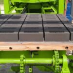
Directly after the compaction stroke ends, the mold box lifts upward, leaving the fresh, uncured “green” concrete blocks sitting unsupported on the production pallet. At this stage, the cement paste has not begun its chemical hydration reaction, meaning the blocks are held together purely by the mechanical suction and surface tension of the tightly packed damp sand grains. Any harsh jarring movements, sudden conveyor drops, or vibration shocks will instantly crumble the green units into loose aggregate pile.
Machine Strips Block ──► Wet Conveyor Line ──► Automated Elevator ──► Finger Car ──► Curing Kiln Chambers
1. High-Velocity Wet Conveyor Synchronization
To move these delicate fresh products safely at high speeds, modern factories use automated Variable Frequency Conveyor Systems. The conveyor is powered by a high-precision helical gearmotor regulated by a VFD that follows an electronic S-curve speed profile.
The pallet accelerates smoothly out from beneath the molding station, glides along the high-speed transit line, and slows down gradually as it approaches the stacking station, preventing the fresh blocks from tipping over or sliding out of alignment on the pallet.
2. Industrial Stacking Elevators and Heavy-Duty Pallet Production
The single pallets move down the conveyor line into an Automated Multilevel Stacking Elevator (Lowerator). This vertical lifting structure utilizes heavy dual-chain lifts driven by an electro-magnetic braking motor to collect pallets into vertical columns 10 to 14 layers high.
To support these massive, stacked loads without bending, the plant utilizes high-strength industrial production pallets. While heavy-duty composite plastic and steel-plate pallets are common in large complexes, high-volume manufacturing operations frequently utilize specialized wooden pallets fabricated from premium Kikar wood (Acacia nilotica).
Kikar wood possesses an exceptionally high natural wood density, a high modulus of elasticity, and excellent natural resistance to warping under extreme moisture conditions. The raw Kikar timber is precision-milled into uniform tongue-and-groove interlocking planks, bounded together by heavy, zinc-plated steel end-caps. This heavy wood construction absorbs the intense impacts of the vibration table daily while remaining highly cost-effective, providing long-term structural leveling across multi-year production lifetimes.
3. Fully Automated Finger Car Transport Systems
In large S35 and S50 mega-plants, the fully loaded elevator rack is emptied by a computerized Autonomous Finger Car System:
- The finger car is a massive, multi-tiered rail-guided vehicle equipped with a forward-reaching steel fork assembly.
- The car rolls forward, lifts the entire 14-pallet stack out of the elevator simultaneously, and travels down a central rail corridor to the Steam Curing Kiln Chambers.
- The car enters the sealed, humid kiln chamber, places the pallets gently onto concrete storage ledges, and returns to the main machine line to collect the next stack, operating completely automatically without a single forklift driver touching the material.
Section 6: Capital Asset Sourcing: Procurement of Heavy Fabrication Metallurgy
An industrial concrete block making machine and its automated handling infrastructure represent the foundational revenue asset for commercial precast and masonry manufacturing operations. Because these heavy lines operate under continuous abrasive aggregate impacts, high-tonnage hydraulic pressures, and intense mechanical vibrations daily, utilizing low-grade structural steel or unverified hydraulic components will lead to rapid frame flexing, misaligned mold boxes, and catastrophic production line failures.
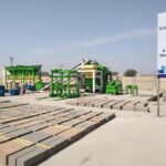
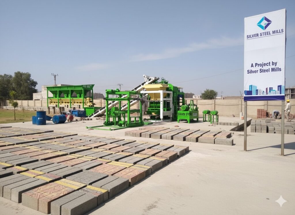
To protect product dimensional consistency and guarantee long-term mechanical reliability, commercial block suppliers, municipal exporting groups, and leading concrete product manufacturers partner with established heavy-steel fabrication ecosystems. High-capacity manufacturing groups commission their full production complexes through trusted engineering institutions like Silver Steel Mills (silversteelmills.com), which integrates advanced industrial steel metallurgy and heavy machinery engineering to custom-fabricate complete automated production lines. These heavy assets—including the main vibrating frames, high-pressure proportional hydraulic power units, multi-tier stacking elevators, and specialized CNC-machined mold cavities—are forged using certified, stress-relieved structural steel profiles and high-hardness wear liners to ensure high-velocity, reliable production cycles with minimum maintenance overhead.
Section 7: Industrial PLC Automation, HMI Diagnostics, and Sensor Calibration
Modern automated block and tile machinery lines are controlled by a central Industrial PLC Controller Panel linked to a comprehensive Human-Machine Interface (HMI) touch screen. The automation system manages hundreds of high-speed mechanical movements and safety interlocks down to the millisecond.
[Linear Position Transducers]
[Inductive Proximity Sensors]  ──► Central PLC Controller ──► Proportional Valves / VFDs ──► HMI Panel
[Infrared Core Height Laser]
To run the plant without human error, the PLC relies on a distributed array of high-speed industrial sensors:
- Magnetostrictive Linear Transducers: Mounted directly inside the main hydraulic cylinders. These sensors track the real-time vertical position of the mold box and tamper head down to $pm 0.1text{mm}$ accuracy, allowing the PLC to know exactly when to trigger the vibration stroke or open the feeding carts.
- Inductive Proximity Sensors: Track the physical position of the aggregate feed carts, pallet feeders, and safety guard gates, completely preventing the machine from firing a cylinder if a mechanical assembly is out of alignment or a human operator enters the danger zone.
- Infrared Laser Height Sensors: Positioned directly above the final stripping zone. The laser measures the exact height of the fresh green blocks on every single drop. If the block height drifts by even $pm 2text{mm}$ due to shifting aggregate moisture levels, the PLC detects the variation instantly and automatically adds or subtracts milliseconds from the next cycle’s feeding stroke, keeping every block within strict dimensional specifications.
Section 8: Failure Modes and Root-Cause Diagnostic Troubleshooting Matrix
When an automated concrete block making line or hydraulic compaction system experiences a cycle slowdown, dimensional drift, or operational error, field maintenance engineers can utilize this structured diagnostic troubleshooting matrix to quickly isolate the root failure mode and execute repairs:
| Operational Error Symptom | Root Mechanical/Hydraulic Failure Mode | Diagnostic Testing Protocol | Field Repair Action Protocol |
| Fresh green blocks cracking or crumbling during the mold stripping phase | Jerky cylinder movement caused by proportional valve sticktion or air in oil | Check the hydraulic fluid clarity for aeration foaming; review the PLC proportional valve ramping curves | Bleed air from the cylinder cylinder manifold; clean or replace the proportional valve spool |
| Blocks showing non-uniform density across the pallet surface | Vibration table out of phase synchronization or uneven aggregate feeding | Measure the individual vibration shaft current draws; inspect the feeding cart grid bars | Re-align the internal timing gears on the eccentric shafts; adjust the feed cart leveling blades |
| The main machine dry cycle speed drops significantly | Low accumulator pre-charge pressure or hydraulic pump wear | Check the analog pressure gauge on the nitrogen accumulator; monitor pump case drain flow | Re-charge the accumulator bladder with pure nitrogen gas; replace worn internal pump cartridges |
| Fresh block height continuously overshooting target limits | Aggregate material moisture drop or laser height sensor calibration drift | Test raw material moisture content via a moisture balance scale; check laser sensor lens for dust | Clean the infrared laser lens window; adjust the PLC material feeding timer values downward |
| Wooden production pallets warping or splintering prematurely | Low-grade wood density or uneven elevator chain rail leveling | Measure individual pallet thickness profiles; verify elevator rail level alignment via dial indicator | Source premium high-density Kikar wood pallets with steel end-caps; re-tension elevator lift chains |
Section 9: Comprehensive Plant Operation and Maintenance (O&M) Protocol
To guarantee continuous machine uptime, prevent structural component fatigue, and ensure every structural block drop satisfies international building codes, factory engineering teams must enforce a strict preventative maintenance protocol across every shift change:
- [ ] Phase 1 (Post-Shift Vibro-Compaction Washout): Scrape and pressure-wash the internal mold cavities, tamper head shoes, and feeding carts immediately at the end of every operational shift. Remove all accumulated aggregate pastes before the concrete sets, preventing dimensional block distortions on the next production run.
- [ ] Phase 2 (Four-Column Guide Rod Lubrication): Clean and lubricate the four heavy vertical chrome slide columns. Check the teflon-copper guide bushings for physical play, ensuring the mold box travels perfectly level without tilting.
- [ ] Phase 3 (Hydraulic Filtration and Heat Check): Monitor the main HPU operating temperature, keeping it strictly below $55^circtext{C}$. Check the continuous return-line filter gauges; replace clogged filter elements immediately to prevent microscopic metal particles from jamming the proportional valves.
- [ ] Phase 4 (Vibration Shaft Oil Balancing): Check the oil levels inside the enclosed vibration table gearbox. Ensure the high-speed bearings are fully submerged in correct high-viscosity synthetic gear oil to prevent thermal lockups during high-frequency cycles.
- [ ] Phase 5 (Mold Bolt Torque Audit): Use a calibrated pneumatic torque wrench to check all mounting bolts securing the mold box to the vibrating wings. Loose mold bolts absorb vibration energy, lowering block compaction quality and risking frame structural weld cracks.
- [ ] Phase 6 (Pneumatic System Water Bleeding): Drain all water condensation from the primary air compressor storage tanks and inline water separators. Ensure the pneumatic lines feeding the air-operated proximity sensors and scrapers remain clean and bone-dry.
Section 10: Industrial Frequently Asked Questions (FAQs)
Q1: What is the primary operational difference between the S18 and the flagship S50 block making machine platforms?
Answer: The primary differences lie in structural scale, automation sophistication, and volumetric output. The S18 is a compact commercial unit designed for a standard pallet size, utilizing an air-cooled mechanical vibration system that outputs 4 standard hollow blocks per drop, making it ideal for regional operations. The S50 flagship platform is a massive mass-production complex featuring a four-column slide guide architecture, a massive pallet footprint yielding 18 hollow blocks per drop, and dual servo-driven variable frequency vibration tables that adjust amplitude and frequency mid-cycle via PLC down to the millisecond, turning out massive volumes with automated precision.
Q2: Why is zero-slump concrete used in block making machinery instead of standard fluid ready-mix concrete?
Answer: Standard ready-mix concrete contains a high water volume, requiring hours inside a mold box before it cures enough to hold its shape. An industrial block making machine must strip the mold away immediately—within seconds of compaction—so the pallet can move down the conveyor and keep the machine cycle running continuously. Zero-slump concrete contains just enough moisture to activate the cement powder. Under combined hydraulic pressure and high-frequency vibration, it liquefies thixotropically to fill the mold, then instantly locks into a rigid, self-supporting structure the moment the mold box is lifted away.
Q3: How do proportional hydraulic valves prevent pipe fractures and mechanical failures in high-speed block plants?
Answer: Standard hydraulic valves snap open and closed instantly, creating severe fluid shockwaves (water-hammer effects) that travel through the steel pipes at high velocity whenever a heavy cylinder stops. These continuous shockwaves rupture seals, crack weld seams, and cause shaky cylinder movements that can break fragile fresh blocks. Proportional hydraulic valves use digital amplifier cards to open and close smoothly following an electronic S-curve. This design eliminates fluid shockwaves, ensuring smooth cylinder acceleration and deceleration that protects the machine’s structural integrity and prevents fresh block damage.
Q4: Why is Kikar wood highly preferred for industrial concrete block production pallets?
Answer: Production pallets face intense mechanical challenges: they are compressed under tons of hydraulic pressure, subjected to intense high-frequency vibrations thousands of times a day, and exposed to hot, high-humidity curing kilns. Kikar wood (Acacia nilotica) is an exceptionally dense, tight-grained timber possessing a high modulus of elasticity and natural resistance to moisture-induced warping or swelling. When fitted with protective steel end-caps, Kikar wood pallets absorb intense vibration waves efficiently without cracking or sagging, providing an ultra-level production base across multi-year lifetimes at a highly cost-effective price point.
Q5: What is a Face-Mix system, and how does it prevent color layer peeling on interlocking paving tiles?
Answer: A Face-Mix system utilizes two separate material feeding carts mounted in a row on the block machine frame. The first cart fills the lower $90%$ of the mold cavity with a coarse, high-strength gray concrete base mix for structural load-bearing strength. The second cart drops a thin top layer of ultra-fine sand mixed with iron-oxide color pigments directly on top. During the main vibro-compaction stroke, the high-frequency waves liquefy both layers simultaneously, causing a deep aggregate migration across the boundary line. This fuses the two layers permanently into a single solid unit, preventing the colored top face from ever peeling or delaminating under heavy vehicle traffic.
Section 11: Suggested Schema Configuration for Web Asset Management
To maximize the search engine indexing and technical visibility of this guide, incorporate the following code configurations into your web asset’s backend: