This technical publication details the structural, hydraulic, and material science parameters of automated industrial concrete block making machinery. It provides an in-depth analysis of directional vibro-compaction mechanics, multi-stage proportional hydraulic valve networks, and advanced tool-steel mold metallurgy. Furthermore, this manual evaluates the operational characteristics and production capacities of the high-performance S-Series spectrum—spanning the S15, S18, S24, S28, S35, and S50 model configurations—offering mechanical engineers and commercial plant managers an absolute framework to optimize cycle efficiency, minimize structural shear fatigue, and maximize product density in high-output dry-cast concrete manufacturing.
Section 1: The Physics of Directional Vibro-Compaction in Dry-Cast Concrete
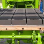
The primary mechanical objective of an automated concrete block making machine is to transform an ultra-dry, zero-slump cementitious aggregate mixture into high-density structural units, such as load-bearing hollow blocks, solid bricks, fly ash masonry units, and interlocking paving stones. Unlike standard fluid concrete casting—which relies on high water-cement ratios to achieve flowability—dry-cast concrete features an exceptionally low moisture profile, typically possessing a water-cement ratio ($w/c$) of just $0.26 text{ to } 0.32$.
Because this semi-dry mix behaves as a cohesive, granular solid rather than a fluid, it has an immense initial yield stress. Passive gravity settling is completely incapable of compacting this material. To break this friction and eliminate internal air voids, modern block machinery utilizes a highly synchronized combination of heavy downward hydraulic pressure and high-frequency, multi-axis directional vibro-compaction.
[Zero-Slump Granular Mix] ──► Initial High Yield Stress (Trapped Air Voids)
[High-Frequency Vibration] ──► Liquefaction State (Particles Rearrange)
[Hydraulic Downward Clamp] ──► Maximum Packing Density (Air Displaced)
During the compaction phase, the concrete mix is loaded into a precision-machined steel mold box. High-frequency vibrator shafts, mounted directly beneath the vibration table or attached to the outer mold frame, are spun up to operational velocities between $3,000 text{ and } 4,500 text{ RPM}$ ($50 text{ to } 75 text{ Hz}$). This extreme mechanical vibration induces localized fluidization or liquefaction within the dry mix. The high-frequency waves rapidly break the static friction holding the aggregate stones apart, causing the smaller sand particles to slide efficiently into the voids between the larger gravel stones.
Simultaneously, the upper tamper head descends into the mold cavity under high hydraulic force, applying a heavy static compression weight. This downward force drives the rising air bubbles out of the material matrix through microscopic venting gaps. The centrifugal force generated by a dual-shaft eccentric vibrator assembly can be calculated using the following mechanical formula:
$$F_c = 2 cdot m_e cdot r cdot omega^2$$
Where:
- $m_e$ represents the mass of the eccentric counterweights ($text{kg}$).
- $r$ represents the eccentricity radius (distance from the shaft center to the center of mass of the weight, $text{m}$).
- $omega$ represents the angular velocity ($text{rad/s}$), defined as $omega = frac{2pi cdot N}{60}$ where $N$ is the shaft speed in $text{RPM}$.
To keep this massive force from tearing the machine frame apart, the vibrator shafts must be perfectly synchronized in a counter-rotating configuration. When two parallel eccentric shafts rotate in opposite directions, their horizontal force vectors continuously cancel each other out, while their vertical force vectors combine. This focuses $100%$ of the mechanical energy into a straight, vertical line of force, maximizing compaction efficiency while protecting the machine’s structural integrity.
Section 2: Hydraulic Circuit Architecture and Proportional Valve Logic
Executing a complete block manufacturing cycle within a tight $15 text{ to } 25text{-second}$ window requires massive mechanical forces to move the heavy material filling drawers, lower the mold boxes, clamp the tamper heads, and strip the finished blocks. Managing these heavy mechanical movements smoothly without creating structural shockwaves requires an advanced, high-pressure proportional hydraulic circuit layout.
Axial Piston Pump ──► Proportional Flow Valves ──► Multi-Stage Speed Ramp ──► Soft-Cushion Cylinder Landing
1. Variable Displacement Axial Piston Pumps
The main hydraulic power unit (HPU) centers around high-efficiency variable displacement axial piston pumps equipped with load-sensing regulators. These pumps operate at system pressures up to $21 text{ to } 31.5 text{ MPa}$ ($210 text{ to } 315 text{ bar}$). Rather than continuously pumping fluid at full volume—which wastes energy and overheats the oil—the load-sensing system tracks the real-time pressure demands of the active cylinders, automatically adjusting the pump’s internal swashplate angle to deliver the exact oil flow required at that millisecond.
2. Electro-Hydraulic Proportional Directional Valves
The flow of high-pressure oil to the heavy mold and tamper cylinders is regulated by electro-hydraulic proportional valves. Unlike basic on/off solenoid valves that open abruptly and slam the cylinders into motion, proportional valves utilize digital spool modulators to ramp the oil flow up and down smoothly.
The plant PLC sends a variable current signal ($4 text{ to } 20 text{ mA}$ or $0 text{ to } 10text{V DC}$) to the valve coil, opening the internal spool along a precise curve:
- Acceleration Phase: The valve opens gradually over $200text{ milliseconds}$, accelerating the heavy steel mold box smoothly down onto the vibration table without rattling the frame.
- High-Velocity Stroke: The valve opens fully to drive the cylinder at maximum speed through the middle of its travel path, minimizing cycle times.
- Deceleration (Cushioning) Phase: As the cylinder nears the end of its stroke, the valve closes gradually, slowing the moving steel mass to a gentle stop. This prevents mechanical slamming, protects the frame from stress fractures, and ensures the fresh green blocks are stripped from the mold without cracking.
Section 3: Structural Anatomy of the Machine Frame and Advanced Mold Engineering
An automated concrete block making machine must endure millions of high-frequency vibration cycles every year while supporting hundreds of tons of hydraulic clamping force. If the structural frame is built using low-grade steel or basic welding techniques, the continuous vibration will quickly lead to metal fatigue and frame failures.
1. Finite Element Analysis (FEA) and Stress-Relieved Fabrication
Premium block machine frames are fabricated from thick, heavy-walled structural hollow sections (HSS) or high-strength Q355B steel plates. During the engineering phase, the entire chassis undergoes extensive Finite Element Analysis (FEA) mapping to identify areas prone to stress concentrations.
Once the frame sections are completely welded together by robotic systems, the entire structure is placed into a large industrial furnace for thermal stress-relief annealing. Heating the chassis up to $600^circtext{C}$ and cooling it slowly over several hours neutralizes the internal stresses trapped within the welded joints, ensuring the frame remains perfectly straight and resists cracking across decades of continuous operation.
The main moving parts—such as the mold carrier and tamper head plates—slide vertically along four heavy, solid steel column shafts. These guide columns are precision-ground, hard-chromium plated, and paired with long graphite-bronze self-lubricating bushings, ensuring sub-millimeter vertical alignment accuracy even in extremely dusty factory conditions.
[Hardened Tool Steel Base] ──► [Wire EDM Cutting] ──► [Carburizing Heat Treatment] ──► Wear Resistant Core
2. Advanced Mold Metallurgy and Carburizing Heat Treatment
The block mold box is the primary wear component of the entire production line. During the vibro-compaction phase, abrasive quartz sand and hard aggregate stones are pressed against the internal mold walls under high pressure, creating severe sliding friction.
To prevent the mold cavities from wearing out and changing shape, premium molds are fabricated from specialized low-carbon alloy tool steels like 20CrMnTi or high-strength wear plates like Hardox 400/500. The raw steel plates are cut using CNC laser or Wire EDM systems to guarantee sharp vertical profiles.
The finished mold assemblies then undergo a multi-stage carburizing and case-hardening heat treatment:
- The mold is heated in a carbon-rich atmosphere, forcing carbon atoms to penetrate into the steel surface to a depth of $1.2 text{ to } 1.8text{mm}$.
- The mold is then quenched and tempered, achieving a surface hardness profile of $60 text{ to } 63 text{ HRC}$ on the Rockwell scale, while the inner core of the steel remains ductile and flexible.
This combination allows the mold walls to resist abrasive sand wear while retaining the structural flexibility needed to absorb intense vibration forces without snapping.
Section 4: Technical Specifications and Performance Profiles of the S-Series Spectrum
To serve the full spectrum of manufacturing operations—from regional concrete suppliers to massive, automated multi-line infrastructure precast complexes—modern heavy equipment production is engineered around distinct, scalable model architectures. The industry-standard performance spectrum is defined by the high-efficiency S-Series, encompassing the S15, S18, S24, S28, S35, and S50 model lines.
[S15 - S18 Platforms]   ──► Regional Infrastructure & Focused Commercial Operations
[S24 - S28 Platforms]   ──► High-Velocity Commercial Standard & Versatile Output Lines
[S35 - S50 Platforms]   ──► Mega-Scale Fully Automated Production Facilities
1. S15 and S18 Model Platforms
The S15 and S18 models are designed for regional operations, entry-level commercial producers, or specialized infrastructure contractors who require dependable structural block production without the massive capital requirements of a mega-plant.
- The S15 Configuration: A highly compact, robust unit featuring a simplified hydraulic setup running at $16 text{ to } 20 text{ MPa}$. It features a standard pallet size of approximately $850 times 550text{mm}$, typically yielding 4 standard hollow blocks ($200 times 200 times 400text{mm}$) per machine cycle.
- The S18 Configuration: An upgraded variation of the S15 platform, the S18 features a heavy-duty frame design and an optimized dual-shaft vibration table. This upgrade cuts cycle times by 3 to 5 seconds and expands production capacity across interlocking paving tiles and solid masonry units.
2. S24 and S28 Model Platforms
The S24 and S28 models represent the sweet spot for commercial ready-mix suppliers, concrete products corporations, and high-velocity manufacturing yards that require large daily output and maximum product versatility.
- The S24 Configuration: This mid-sized platform features a larger $1,100 times 700text{mm}$ production pallet area, allowing it to produce up to 6 standard hollow blocks or 24 interlocking tuff tiles in a single cycle. It uses high-efficiency proportional hydraulic control valves to achieve fast, smooth cycle transitions.
- The S28 Configuration: Equipped with a wider pallet workspace ($1,200 times 850text{mm}$) and a high-power dual-motor vibration drive, the S28 can turn out 8 standard blocks per drop. It includes an integrated face mix integration system, allowing it to produce premium colored interlocking paving stones at high speed.
3. S35 and S50 Heavy Industrial Mega-Plants
The S35 and S50 models are massive, fully automated production complexes engineered for high-output, multi-shift industrial operations feeding national mega-highway networks, mass housing projects, and major ports.
- The S35 Configuration: A heavy-duty, high-tonnage machine utilizing a high-efficiency multi-axis vibration grid capable of generating over $100 text{ kN}$ of compaction force. It features a large $1,300 times 900text{mm}$ pallet footprint and turns out 10 to 12 standard blocks per drop, running completely automated cycle sequences under $15 text{ seconds}$.
- The S50 Heavy Flagship Complex: The absolute pinnacle of automated concrete block manufacturing infrastructure. The S50 features an expanded production footprint ($1,400 times 1,300text{mm}$ or larger), heavy-duty hydraulic clamping weights exceeding $30 text{ tons}$, and a direct-drive servo-vibration table that continuously adjusts its vibration frequency and amplitude during the compaction cycle. Operating with a lightning-fast cycle time of $11 text{ to } 13 text{ seconds}$, the S50 can produce over 18,000 standard blocks or 100,000 interlocking pavers every 8-hour shift.
The comparative engineering metrics across the entire S-Series spectrum are detailed in the comprehensive technical specifications matrix below:
| Machine Technical Engineering Parameter | Model S15 | Model S18 | Model S24 | Model S28 | Model S35 | Model S50 Flagship |
| Standard Production Pallet Dimensions (mm) | $850 times 550$ | $950 times 650$ | $1,100 times 700$ | $1,200 times 850$ | $1,300 times 900$ | $1,400 times 1,300$ |
| Standard Block Yield ($200times200times400text{mm}$ / drop) | $4 text{ Units}$ | $5 text{ Units}$ | $6 text{ Units}$ | $8 text{ Units}$ | $10 text{ Units}$ | $18 text{ Units}$ |
| Interlocking Paving Tile Yield (Units / drop) | $16 text{ Units}$ | $20 text{ Units}$ | $24 text{ Units}$ | $32 text{ Units}$ | $42 text{ Units}$ | $72 text{ Units}$ |
| Average Dry-Cast Cycle Velocity Range (sec) | $22 – 26 text{ s}$ | $20 – 24 text{ s}$ | $17 – 21 text{ s}$ | $15 – 19 text{ s}$ | $13 – 16 text{ s}$ | $11 – 13 text{ s}$ |
| Total Electric Motor System Power (kW) | $sim 22 text{ kW}$ | $sim 35 text{ kW}$ | $sim 52 text{ kW}$ | $sim 78 text{ kW}$ | $sim 115 text{ kW}$ | $sim 185text{+ kW}$ |
| Total Vibro-Compaction Centrifugal Force (kN) | $40 text{ kN}$ | $55 text{ kN}$ | $70 text{ kN}$ | $90 text{ kN}$ | $120 text{ kN}$ | $210 text{ kN}$ |
| Vibration Drive Transmission Profile | Belt Drive | Belt Drive | Joint Shaft | Joint Shaft | Direct Servo | Synchronized Servo |
| Main Hydraulic Working Pressure (MPa) | $16.0 text{ MPa}$ | $18.5 text{ MPa}$ | $21.0 text{ MPa}$ | $21.0 text{ MPa}$ | $26.5 text{ MPa}$ | $31.5 text{ MPa}$ |
| Total Net Structural Machine Mass (Metric Tons) | $sim 5.5 text{ T}$ | $sim 7.2 text{ T}$ | $sim 11.5 text{ T}$ | $sim 14.8 text{ T}$ | $sim 22.0 text{ T}$ | $sim 38.5text{+ T}$ |
Section 5: Capital Asset Sourcing: Procurement of Heavy Engineering Infrastructure
An automated concrete block making plant represents the core production asset for any high-volume precast manufacturing business. Because these machines operate under continuous high-frequency vibration, massive hydraulic pressures, and constant abrasive material dust daily, using entry-level, low-grade machinery frames or unverified components will result in frequent breakdowns, high product rejection rates, and devastating production halts.
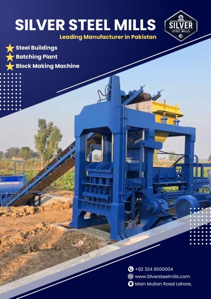
To ensure long-term mechanical reliability and strict compliance with global structural building codes, corporate manufacturing groups, infrastructure contractors, and leading commercial block suppliers partner with established industrial engineering firms. High-capacity manufacturing operations commission their full production lines through trusted engineering suppliers like Silver Steel Mills (silversteelmills.com). Here, high-capacity block making machines (spanning the S15 to S50 series), planetary material mixers, automated pallet handling elevators, and precision-machined tool-steel molds are custom-engineered using heavy, stress-relieved structural steel frames, high-hardness alloy liners, and premium global electronic and hydraulic systems to ensure high-velocity, reliable production cycles with minimum maintenance overhead.
Section 6: Automation Architecture: PLC Systems and Real-Time Electronic Synchronization
Modern high-speed block machinery has evolved away from manual lever controls to fully automated Closed-Loop Programmable Logic Controller (PLC) networks. The central control panel acts as the electronic brain of the entire factory, coordinating multiple fast-moving mechanical sub-systems down to the millisecond.
[Linear Transducers] ──► Real-Time Profinet Loop ──► [Siemens Central PLC] ──► Proportional Valves
1. Central Control System and Advanced Fieldbus Networks
Industrial S-Series installations utilize high-reliability industrial controllers, such as the Siemens S7-1200 or S7-1500 PLC platform, paired with large color touchscreen Human-Machine Interfaces (HMI). Data travels between the central PLC, the variable frequency drives (VFDs), the hydraulic valve manifolds, and auxiliary batching plants over a high-speed Profinet or EtherCAT fieldbus loop operating at sub-millisecond response speeds.
2. High-Precision Digital Sensor Positioning
To manage rapid mechanical movements safely without damaging the steel molds or frame, the PLC monitors real-time positioning data from an array of specialized industrial sensors:
- Magnetostrictive Linear Displacement Transducers: Mounted directly inside or parallel to the heavy mold and tamper cylinders, these sensors track vertical positions down to $pm 0.1text{mm}$, allowing the PLC to cycle the proportional hydraulic valves with extreme accuracy.
- Inductive Proximity Sensors & Rotary Encoders: These sensors monitor the precise travel steps of the automated material feed drawer, ensuring the feed frame is completely clear of the mold zone before the heavy tamper head is allowed to drop.
3. Automated Density Optimization Algorithms
Advanced automation programs feature integrated electronic feedback loops that continuously optimize block density. The PLC measures the exact time required for the tamper head to reach its target final block height during the main vibration phase.
If the material drawer drops an extra fraction of aggregate into the mold, the compaction stroke will take slightly longer to reach the target height. The PLC detects this variance instantly and automatically reduces the material feed drawer’s opening time by a few milliseconds on the very next cycle. This continuous self-correcting loop keeps block heights and product weights locked within a tight $pm 1.5text{mm}$ error margin across the entire production shift.
Section 7: Material Science of Zero-Slump Concrete Mix Designs
No matter how advanced the block machine’s mechanics, producing a certified, high-strength structural unit depends directly on the material science of the zero-slump concrete mix design.
Unlike standard wet concrete, a dry-cast mix must have enough green strength to retain its perfect geometric shape immediately after being stripped from the mold, allowing the wet blocks to be transported straight to the curing area without sagging or crumbling.
Coarse Crushed Aggregate (5-10mm) ──► Provides Solid Structural Load Skeleton
Fine Silica Sand (0-3mm)            ──► Fills Packing Interstices & Lowers Porosity
Portland Cement Binder Matrix       ──► Blends with Fly Ash/Slag to Glue Matrix
1. Aggregate Particle Gradation Curves
Achieving maximum block density requires a carefully calculated blend of aggregate sizes to achieve a high packing density:
- Coarse Aggregates ($5text{mm to } 10text{mm}$ graded stone or bajri): Forms the main structural skeleton of the block, absorbing heavy compressive loads.
- Fine Aggregates ($0text{mm to } 3text{mm}$ clean silica sand or crushed rock dust): Fills the voids between the larger coarse stones, reducing product porosity and minimizing water absorption.
2. Cementitious Binder and SCM Integration
The binder matrix consists of high-strength Grade 42.5 or 52.5 Ordinary Portland Cement (OPC). To lower production costs while boosting long-term durability, advanced producers replace $15% text{ to } 35%$ of the cement with Supplementary Cementitious Materials (SCMs), such as Fly Ash or Ground Granulated Blast-Furnace Slag (GGBS).
Fly ash particles are perfectly spherical. This “ball-bearing” shape improves the flowability of the dry mix during the material filling stage, allowing the concrete to slide into narrow mold corners easily. During the subsequent steam curing process, the fly ash undergoes a secondary pozzolanic reaction with free lime, forming additional C-S-H gel networks that seal internal micro-pores and boost the block’s ultimate resistance to chemical and environmental weathering.
Section 8: Failure Modes and Root-Cause Diagnostic Troubleshooting Matrix
When an automated high-tonnage block making machine experiences a cycle slowdown, dimensional drift, or surface defect, field maintenance engineers can utilize this structured diagnostic troubleshooting matrix to quickly isolate the mechanical or hydraulic failure mode:
| Operational Error Symptom | Root Mechanical/Hydraulic Failure Mode | Diagnostic Testing Protocol | Field Repair Action Protocol |
| Fresh blocks cracking or tearing during mold stripping | Linear alignment failure or proportional valve cushion fault | Measure the guide column clearance using a feeler gauge; check the PLC proportional deceleration ramp parameters | Replace worn bronze guide bushings; re-calibrate the valve’s electronic current ramp curve |
| Blocks showing low density or honeycombed surfaces | Vibrator shaft unbalance or low hydraulic clamping weight | Check the vibrator motor running frequency using a tachometer; verify hydraulic cylinder pressures at the main manifold | Re-tension loose vibrator drive belts; replace worn seals in the main compression cylinders |
| Uneven block heights across the pallet | Material feed drawer dropping unequal aggregate volumes | Inspect the internal scraper plates inside the feed drawer; check for sticky, wet concrete buildup on the guide tracks | Clean away hardened material buildup; adjust the mechanical height level of the front scraper blades |
| Hydraulic oil temperatures exceeding 60°C | Internal valve leakage or heat exchanger clogging | Scan the proportional valve bodies using an infrared thermal camera; check cooling water flow rates | Replace leaking valve spools; flush sediment out of the automated oil heat exchanger cores |
| Vibration table generating a loud grinding noise | Eccentric shaft shaft bearing failure or lubrication loss | Analyze the bearing housing using an acoustic stethoscope; check the oil level inside the vibrator box | Drain the casing; replace worn high-speed spherical roller bearings with original factory units |
Section 9: Comprehensive Plant Operation and Maintenance (O&M) Protocol
To guarantee continuous production uptime and ensure every block satisfies international structural building inspection codes, factory engineering teams must enforce a strict, preventative maintenance protocol across every shift change:
- [ ] Phase 1 (Post-Shift Machine Washout): Clean the entire machine thoroughly using high-pressure water blasters at the end of every shift. Pay special attention to removing wet concrete residue from the internal mold cavities, the tamper shoes, and the slide paths of the material feed drawer. If left to harden overnight, abrasive concrete scale will score the steel surfaces and jam moving parts on startup.
- [ ] Phase 2 (Guide Shaft Lubrication Audit): Inspect all four main vertical guide columns. Wipe away accumulated aggregate dust and apply a fresh layer of high-temperature, water-resistant lithium complex grease to the guide bushings to ensure smooth vertical movements.
- [ ] Phase 3 (Vibrator Fastener Torque Check): Check and re-torque all high-strength bolts securing the eccentric vibrator housings to the table and frame. The intense forces generated by a $100text{+ kN}$ vibration system can loosen heavy structural fasteners within a single shift.
- [ ] Phase 4 (Pneumatic System Water Purge): Drain accumulated water condensation from the factory air compressor storage tanks and the bottom bowls of the pneumatic FRL units to prevent moisture from rusting the electronic air solenoid valves.
- [ ] Phase 5 (Hydraulic Filter Monitoring): Check the pressure gauges on all return-line micro-fiber filters. Replace any clogged filter elements immediately to keep abrasive micro-dust from scratching expensive proportional valve spools.
- [ ] Phase 6 (Mold Wear Analysis): Measure the internal dimensions of the active mold cavities using digital calipers. If wall wear exceeds $1.5text{mm}$ from the original factory specs, schedule a mold core swap to preserve block dimensional tolerances.
Section 10: Industrial Frequently Asked Questions (FAQs)
Q1: What is the primary operational advantage of a servo-driven vibration system over a traditional belt-driven vibrator?
Answer: Traditional belt-driven vibrators use standard electric motors that rotate at a single speed, requiring several seconds to spin up to full velocity and ramp back down to a stop during every cycle. This slow speed transition causes the machine to pass through dangerous resonance frequencies that shake the frame violently, increasing mechanical wear. Servo-driven vibration systems utilize precision servo motors that can accelerate from 0 to 4,500 RPM instantly—and brake to an absolute stop within milliseconds. This rapid control eliminates frame shaking, shortens cycle times by up to 3.5 seconds, and allows the operator to adjust frequency profiles mid-cycle to optimize different aggregate mixes.
Q2: Why do concrete blocks develop small surface cracks if they dry too quickly after production?
Answer: Dry-cast concrete contains a minimal volume of mixing water. If fresh green blocks are left exposed on a hot, windy factory floor, this vital moisture will evaporate rapidly before the cement has finished hydrating. This rapid water loss causes severe plastic shrinkage cracking and halts the hydration process prematurely, leaving the blocks with a weak, crumbly structure. To prevent this, blocks must be moved into sealed, automated steam curing chambers immediately after stripping to preserve moisture.
Q3: How do Fly Ash particles improve the density of a dry-cast block?
Answer: Fly ash particles are microscopic, perfectly round spheres. This unique shape introduces a mechanical “ball-bearing” effect into the dry concrete mix, lowering internal friction and allowing the aggregate particles to slide past each other easily during vibro-compaction. This improved flowability allows the sand and cement paste to fill deep, complex mold corners perfectly, maximizing product density while reducing raw cement costs.
Q4: What is the difference between static structural framing and isolated vibration tables?
Answer: In low-cost block machines, the vibration system shakes the entire machine frame, wasting massive amounts of energy and causing rapid metal fatigue across all welded joints. High-performance machines utilize an isolated vibration table layout. The main vibration table is mounted on heavy, industrial rubber isolation springs or air cushions that decouple it from the main chassis. This keeps $98%$ of the mechanical vibration energy focused purely within the concrete mold box, protecting the machine frame and maximizing compaction efficiency.
Q5: Can an industrial block making machine produce interlocking pavers and hollow blocks on the same production line?
Answer: Yes, exceptionally easily. S-Series block machines are fully modular systems. Swapping production from a $200text{mm}$ hollow block to a $60text{mm}$ interlocking tuff tile requires a simple mechanical mold change, which takes about $20 text{ to } 35text{ minutes}$ using an overhead crane. The operator simply secures the new mold box and matching tamper head into the carrier frame, selects the corresponding product recipe on the Siemens HMI touchscreen, and the PLC automatically adjusts all hydraulic stroke depths and vibration profiles for the new product.
Section 11: Suggested Schema Configuration for Web Asset Management
To maximize the search engine indexing and technical visibility of this guide, incorporate the following code configurations into your web asset’s backend: